Automation in Tube Benders
Many documents have been written through the years on how to bend tubing on a tube or pipe bender, and all have been accurate for the time in which they were written. I say that because tube and pipe bending has evolved over the years, and the most significant evolutions have transpired in the last twenty years.
In the early '90s, most automotive bending Centerline Radii (CLR) were above 1.5D. They had plenty of straight sections between bends so that a standard 2D clamp and insert would be sufficient for all bends in those components being bent. A 2D clamp and insert (length) = ( 2 X the tube O.D.).
The Pines benders are very rigid, easy to set up, and worked well for 1D bending, but unfortunately, the 1D bending was only used to bend elbows or single bends. Then they were welded into straight sections to produce the complete component, which is very time-consuming.
The automotive industry at the time hadn't started the big push to lighten cars and make them more efficient. The tubing was 1.5-2mm thick, and if you were bending 1.5mm wall tubing in the '90s, some considered that “thin wallâ€.
You could still sit on the fender of your Dodge Ram or GMC pickup, with your feet on the wheel well, and change the spark plugs, so there was still a lot of room under the hood of American-made vehicles that were not being utilized.
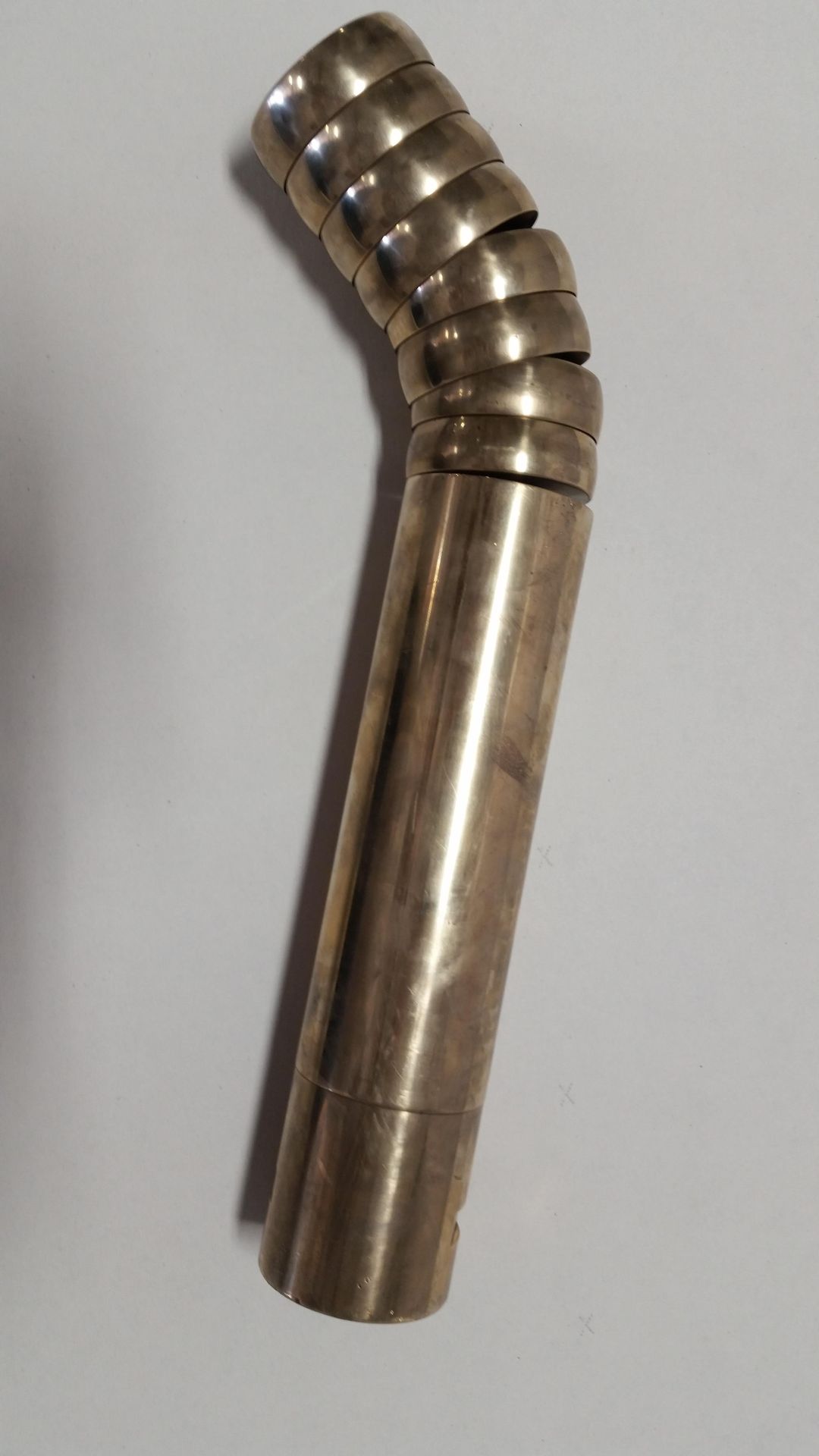
The early to mid-90s was when I saw the straights between bends shorten below 2D, and stack benders become the coveted machines of the time. The early stack machines were either a 2-stack or a 3-stack.
The stack heights were fixed, as opposed to today's highly evolved machines which are multi-stack, meaning they have a limited stack height, but as long as the number of stacks could be placed in the height range, it would work.
On a 3-stack machine, you could only have a straight clamp and two contours, so it still limited the automotive industry in how many short straights they could have in the vehicle components, or that component became very labor-intensive because the component would have part of it bent on one bender setup. The balance bent on a second setup.
The auto industry also followed the aircraft industry by reducing the bend radii of the bends in components, bringing on the next rage in tube benders. Which was “Boost bendingâ€.
This allowed for multiple 1D bends in a single component, as opposed to using a Pines bender, where the elbows were bent and then welded to straight pieces, comprising the complete component. Now, it could all be done on one machine, well, almost.
In the late 90s, another innovation came along to further aid production and save material: cutting the tube after bending. So, bender manufacturers developed various types of “bender cutoffs,†all of which have advantages or disadvantages.
Some of the disadvantages were only realized after implementation into production. One of the disadvantages is that trimming the tube on the bender utilizes more bender time, so less tubing was bent because bender time was taken up by the trim, or parting process. So, industries learned quickly that if it doesn't have to be cut or trimmed on the bender, do it in a second operation, thus allowing the bender to bend more parts than before.
Today's standard material wall thickness is 1mm, and I have worked on developing multiple 90-degree bends on a 69.9 O.D. X 69.9CLR X 0.8mm W.T. for an OEM supplier last year, so 0.8mm wall material is soon to come.
Standard material thicknesses for aircraft material are .035â€, .032â€, .028â€, and .021â€, some of which are much less than automotive. However, the material types are much better to bend. Aircraft materials are Inconel, Titanium, 304SS, and T6061 aluminum in various heat treatments.
Again, most of these require more pressure from the pressure die to make good bends without wrinkles, and the wiper tower needs to be rigid enough to maintain position when this additional force is applied.
If you have experience setting up benders, you know that a wiper post or tower that deflects during bending creates multiple problems, such as wrinkles.
The setup person has difficulty setting the wiper because all the rules he or she knows no longer apply, and uncertainty sets in on how to set the wiper on a post that moves during bending.
If you bend 1D bends on your bender, set the wiper with a negative rake, and get good bends (no wrinkles), I can assure you that something is moving on your wiper tree! If you are doing 1D bends and producing excess scrap from wrinkles,
I urge you to investigate if your wiper post or tower is deflecting, and if it is, I suggest replacing it with a heavy-duty tower or post.
The cost of a multi-stack heavy-duty wiper tower can be expensive when you look at the price, but weigh it out against the scrap produced and downtime due to setup issues, and quickly you will realize the cost is justified in many cases. Once the wiper tower is rigid, you will see your scrap reduced and productivity elevated.
If you have questions about CNC tube bending dies, please let us know, and one of our experts will be in touch.